Aegis Radiosity Engine
Aegis' radiosity engine uses a global illumination style lighting to light the environment. The following will be an overview of the algorithm used to render the images found in the results section.
The algorithm is very simple and straight forth once you remove a lot of the math. Before we get into the algorithm there are a few terms that should be understood.
- Incident = I
- Amount of light that a patch receives
- Reflectance = R
- Multiplier for how much light is reflected back into the world
- Emission = E
- Amount of light that the patch emits
- Excident = Ex
- Amount of
light that exits the patch
- Ex = (I * R) + E
This is the the basis of radiosity lighting. Where the the amount of light that a patch will emit is equal to the amount of light it receives multiplied by the amount of that it is allowed to release or reflect back into the world, plus the amount of light the object itself emits. Although we have just covered the very basic formula here, there is still a series of steps that must be taken to generate values. First we will start with the Basic algorithm of the Radiosity engine and then go into each with more detail. By the end of this you should have a good understanding on how to write a Radiosity lighting solution.
The Algorithm
The main algorithm is very small and simple:- Initialize the system
- Main Loop
- Loop for N Passes
- Collect light from scene
- Calculate Excident light
- Raytrace scene
with calculated light
Although this seems very straight forward there is some fine details that need to be discussed.
Initialize the System
At the start we need to initialize all the patches in the scene
- For Each Patch in the Scene
- If the patch emits light
- Set the patch emission to light colour
- Else
- Set the patch emission to black
- Set Excident to equal Emission
Collect Light from Scene
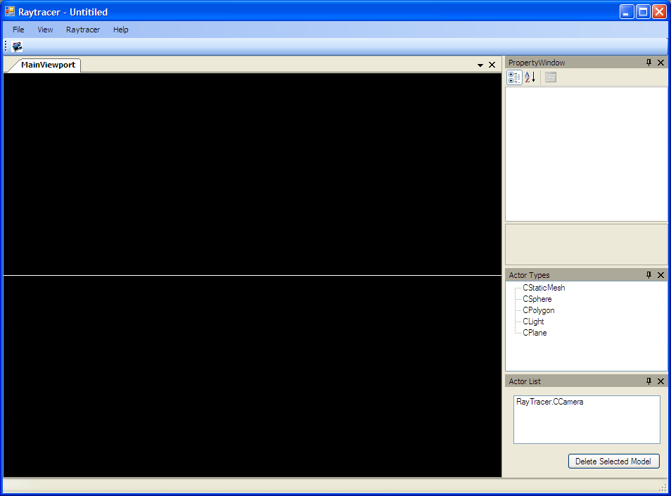
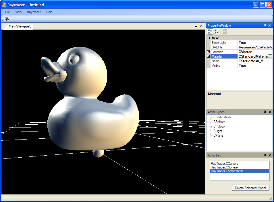
To calculate the lighting for the scene we need to render a hemicube for each patch and then multiply the result by a filter. First lets figure out what the hemicube is. Below is screen shot of a polygon in the middle of our scene with some spheres around it. What we are going to do here is determine what the hemicude looks like for the polygon when the normal is facing the purple sphere.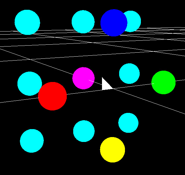
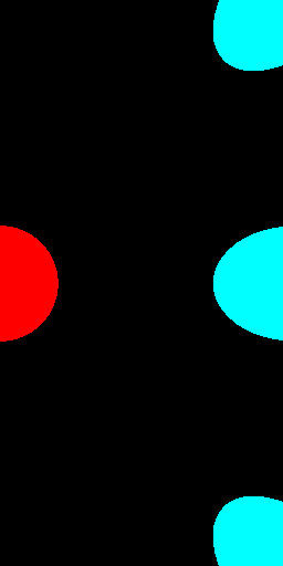
To generate a hemicube we must render 5 views. Front, Top, Right, Bottom, and Left. To do this you simply rotate the camera 90 degrees each way and render the scene. When rendering the Top, Right, Bottom, and Left view we only take half of the image. Below are the images that our hemicube should render (doing this pass does not require using the raytracer, you can use OpenGL or DirectX to render our scene, just make sure you use flat shading).

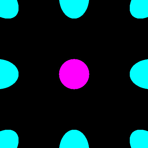

Once your hemicube images are rendered you then need to filter them. Using Lambert's cosine law we will generate filter that looks like the following (ignore the black corners, they are not used in our final calculation):
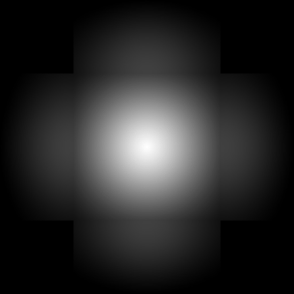
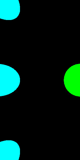
Now this i a very important step and can be done early on (probably around the initialize stage and you are getting things setup). You MUST normalize the map. So, add all the pixels together and then divide each. this will cause the center to be a lot darker, but will allow the engine to converge in the end. If you do not normalize your filter your scenes will receive too much light and possible be all white in the end (or the dominate colour in your light). Once you have your filter and hemicube images you multiply them together to get your final hemicube light as seen below (for this image I did not normalize the filter so we can see the results a little clearer):
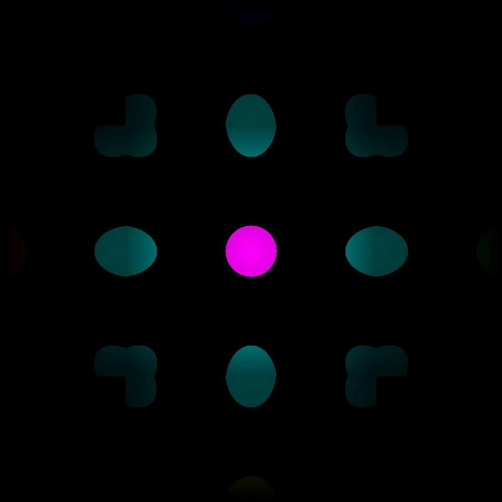
Now that we have our final image we can add all the values in this to get our final light. This value is assigned to the patches Incident light and then we move onto the next patch. This stage must be done for each patch in the scene and is the slowest part of the radiosity lighting. You must also do this stage several times, at each stage more patches start to receive light and your room will start to illuminate.
Calculate Excident Light
Our final step in the main loop is to calculate the excident light. Remember our equation from above:
- Ex = (I * R) + E
Results
The results for the radiosity can be found here.
After thoughts...
At first a lot of books make this out to be over complicated when this is actually a simple algorithm to implement (some algorithms may be different though), but once you get into writing your radiosity lighting you will find it to be not that bad. There is one thing to keep in mind when you are going to do this and that is,; this algorithm is not fast. Below are some times approximate times that it takes to render some scenes using the algorithm that was described above.
Language: C#
Radiosity lighting: XNA
Processor: Xeon(TM) CPU 3.73 GHz, 4GB of Ram
| Polygons in Scene | Render Time | Total number of Passes |
| 350 | 3 minutes | 5 |
| 9,128 | ~1 hour 10 minutes | 5 |
| 75,008 | ~20 Hours | 5 |
References
Radiosity, by Hugo Elias (a general overview of the lighting algorithms that was used in this project)
Helios32 Radiosity: a Programmer's Perspective by Ian Ashdown (1994). This book is free also..
Radiosity In English: Another simle break down of radiosity.
Radiosity, the ever famous wiki.
Hemicube, again our famous wiki.
Radiosity Overview Part 1. SIGGRAPH 1993 Education Slide set, by Stephen Spencer.