Click here to see the animation!!
Click here to see a high resolution image of the model.
As this occurs the camera suddenly jerks to its right and notices a ball held up on some mechanism, attached to the clock. As the camera approaches this ball, a double door mechanism opens and allows it to descend. At this time it becomes a target for another camera, and here we have our first camera cut, as the 2nd camera races to catch up with the ball in its descend.
Just as the ball gets close to colliding with a metal plate structure, there is a quick camera cut to get the ball's collision with this object from underneath. This collision sets off a reaction where it releases a piece of paper which is supported by another double door structure. As we follow the ball, it lands on a seat like support to break it's fall and direct it to a tube close by.
Then after it rolls down the tube, gaining velocity, as the next camera, number 3, records it's path. Next after completing its descent down a tube, the ball, traveling at high speed, lands on 3 switches in succession. This slows down the ball and gets it back into control.
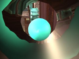
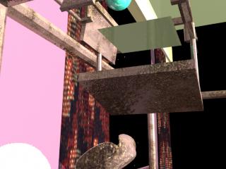
Now at the end of the 3rd switch, it enters an enclosed tube, which is more vertically inclined, therefore helping the ball pick up some of the velocity it needs for the latter part of the machine. A camera cut occurs here, and this new recording device is placed on a motion path so it can follow the ball. For the next little while the camera follows the ball quite closely through this enclosed tube. A spotlight had to be added to the same motion path as the camera, since light was needed within the tube.
As all of this is occurring the piece of paper which was able to descend with the help of the ball has fallen toward the base of the machine and is ready to be stamped.
In the last phase of the machine, the ball comes out of the tube, travels in mid air for a little while, and as it is descending, knocks a switch. This switch is important in that it is connected to a small gear structure which is forced to turn because of the sudden jerk of the switch and ball collision. As this small gear rotates, it forces a larger gear above it to rotate also. This larger gear indirectly moves two adjacent counters which are used to stamp the year on the card. Soon after, the print head falls on the card, thereby stamping the card with its greeting.
Lastly, the card falls through another door and slides to a position
in front of the machine on the desk.
The main components of the machine were the ball, paper release doors, paper, paper door trigger, and trigger dampers. The paper door trigger was partly under the paper release doors. The trigger was hinged at the opposing end and also had a spring pulling it upwards. The arrangement was such that unless the trigger was moved downwards, the paper door would not release the paper. The dampers were placed to stop the trigger from spinning out of control.
The catch tray for the paper was created by extruding a polygon cube and turning it into a passive rigid body. A similar tray was created lower to catch the paper and guide it under the press.
An extruded polygon was smoothed to create a soft landing pad for the ball. The pad was positioned to allow the ball to proceed in the direction of the tube. This pad proved extremely useful after the rigid body solver showed some non deterministic tendencies. The tube was created by extruding a cross-section curve with a profile curve.
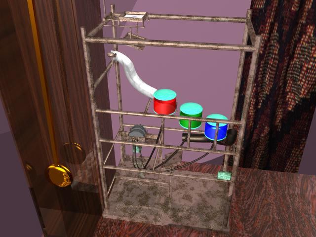
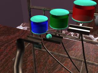
The ink bottles were created by revolving curves. The ink switch, which was duplicated twice, consisted of a rigid body shaped to guide the ball. The switch was an extruded polygon and was constrained by a spring and hinge similar to the paper trigger.
The 3 successive ink switches were placed to allow the ball to reach the tube at the end. The realism of the rigid body solver is such that the ball loses a lot of kinetic energy by the time it reaches the tube. The second tube was constructed with the same procedure as the first one. It was profiled to allow a maximum gain in kinetic energy of the ball.
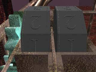
The counter increment trigger was an active rigid body. It was created by scaling alternate vertex points. The counters were created with polygon cylinders. All of these were hinged on the same axis.
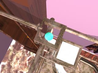
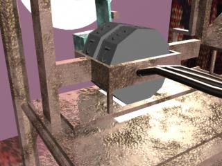
The printing block was created by extruding a polygon. Which was then turned into an active rigid body. The downward motion of the press was caused by gravity. The block was guided by rails that were created (by extruding a poly cube) as a part of the landing base for the press.
The release door for the printed card was created out of a polygon cube and was constrained by a hinge. After the press landed, the door was released to allow the paper to slide out.
The ink tubes were created similar to the motion tubes. The joint tool was then used to create a skeleton with the root at the respective bottle. The skeleton was bound rigidly to the surface and an IK handle was placed with the end at the press.
After modeling this segment, the machine's rigid body motion was baked into key frames. The key frames then had to be "cleaned" since the baking process creates a key for every rigid body for every frame.
The support structure for the machine was created entirely out of scaled polygon cylinders with the occasional scaled cube. A starting mechanism was placed which opened a door for the ball to fall through and begin the baked simulation.
Lights:
The animation uses 1 ambient, 2 diffuse, and 2 spotlights. A special spotlight is used to illuminate the ball inside the second tube. The special spotlight is animated along a motion path to follow the ball.
Textures:
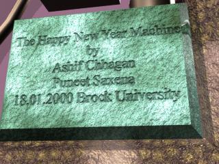
This model uses many different forms of texturing. From files to bump maps, we tried to incorporate a wide range of them. As can be seen from our model, which tries to emphasize the importance of texturing. This model also incorporates three bitmaps made in Adobe Photoshop. We used bit mapping to texture our counter structure, the writing on our card and the final plaque for our closing scene. Just as a note, Ray Tracing was turned on for every frame in our animation,
Conclusion:
Computer animation is a great way to express one's creativity. Advances
in modeling techniques and processing speed have made it possible to create
complex animations with relative ease. The basic challenge of creating
an effective animation that captures its audience, however, is still answered
by the animator. Using Maya has been a memorable experience of effectively
using a software with almost unlimited capabilities. It has been an exercise
in lateral thinking, computer graphics fundamentals, patience, and creativity.
In the end, we are happy that we got an opportunity to use such a program,
and express some original ideas.